 |
| Circuit Schematic |
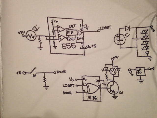
To make the operation reliable, we need to add some hysteresis to the light sensor output. The subcircuit in the upper left of the schematic shows how this is done. A 555 can be used as a Schmitt trigger by tying the inputs of both op-amps (pins 2 and 6) together. This creates a trigger that will go high when the input voltage crosses two thirds of the supply, and low when it goes below one third of the supply. The voltage divider to create these reference voltages is built into the 555 as a set of three matched resistors.
The light level is converted into an unstable voltage level using a simple voltage divider. I used a 100K resistor on the pull-down side, to match the dynamic range of my CdS photoresistor. Combined with the 555 Schmitt trigger this provided a stable logic signal with hysteresis reflecting the ambient light level.
Detecting the door position was simple. I connected the micro-roller switch to a pull down resistor to create the door logic level directly. Because the output of the entire circuit is physical motion, I wasn't worried about debouncing or other processing of the switch signal.
The output stage combined the DOOR and LIGHT signals as inputs to one of the four XOR units on the 7486. The 7486's output stage can't deliver enough current to run the motor, so I had it drive the NPN BJT 2n2222 instead. The 2n2222 is able to deliver up to 800mA, which is plenty for this application. I added an indicator LED to show when the motor was energized, so I could test the sensing without attaching the motor. The flyback diode attached to the motor is a 1N4003, and protects the rest of the circuit from voltage spikes caused when Q1 shuts off and the motor acts as an inductor trying to drive a high impedance load, potentially causing a damaging voltage spike as the field collapses.
Battery power was regulated by a low dropout 5V regulator, an LF50ABV in this case. I should have used an LM317 to regulate the solar cell output voltage to the float voltage of the VRLA batteries (~7V). Because my original cell didn't supply enough current to drive the LM317, I used an alternate hack, the stack of LEDs, which should limit the voltage to the battery to around 7V. They'll start to conduct limited current when the cell voltage is below the battery voltage, resulting in inefficient charging. Hopefully, because the charging needs of this device or minimal, there's enough excess power from the cell that the battery will remain charged.
Time will tell.
No comments:
Post a Comment