The first design that came to mind was to avoid having any linkages at all and simply place a disk with a hole in it on a drive shaft. To open, it would rotate until the hole lined up with the opening to the feeder, and rotate again to close the feeder. This is simple, but for a relatively large opening the size of the disk becomes a big unwieldy. If the disk isn't flush against a support surface any overhang could catch and place a large axial load on the drive shaft, potentially jamming or damaging it.
 |
| First design idea for access control mechanism |
I like the idea of covering and uncovering and opening in the feed hopper, but directly moving the cover by rotating it is too bulky. Instead, I want to produce simple linear motion from the rotation of the drive shaft. One simple way to do this is to use a slider-crank mechanism.
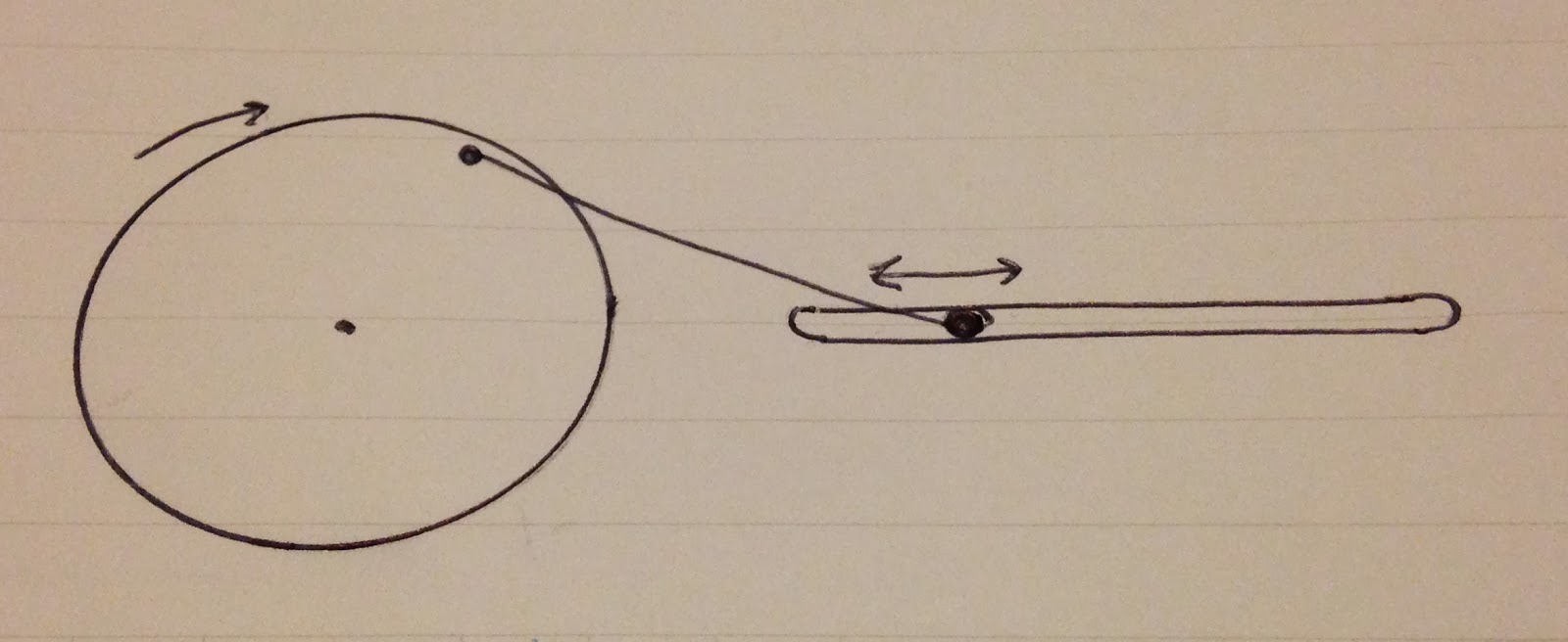 |
| Slider-crank mechanism |
The linear displacement from this mechanism will be equal to the distance from the drive shaft's axis to the linkage attachment point. Realistically, this lets me open a feed slot about 5cm given a 6cm drive wheel. Next, I need to figure out how to sense when the feed slot is open or shut.
A typical approach to sensing the feed slot position would be to use a pair of limit switches. When the slot was open it would trigger one limit switch, and when closed it would trigger the other. This seems like too many switches, since there's only one bit of state to be sense (open or shut). It also makes the logic for when to turn on the drive motor complicated, since there are three input signals (ambient light and two limit switches) rather than two.
Worse, since the logic for the two limit switch solution requires the motor to be on whenever the door is in an intermediate state, it's possible that if the door moves too quickly, or has too much inertia to stop while the limit switch is triggered, the door could just run forever. This is unlikely, but it requires tracking more variables, like the feed-door overlap and the drive train backlash, to make sure the door will reliably stop with the feed-door functionally closed.
 |
| Half-wheel for sensing open and shut feed slot |
Instead, I'll use a design with a single limit switch. By cutting the drive wheel in half, the switch will be on during half the rotation of the drive shaft, and off for the other half. By moving the switch we can change where in the cycle the switch changes state. This makes the control logic simple. When the switch is on the door is shut or in the process of opening, and when the switch is off the door is closed or in the process of opening.
The control logic is a single XOR between the ambient light sensor and the door switch. If it's light and the door is shut or in the process of opening, energize the motor. If it's dark and the door is open or in the process of closing, energize the motor. Otherwise, don't turn on the motor. Simple.
I found a nice 6V DC miniature motor with a serious looking output reduction on one of my favorite surplus sites, MPJA. It's pretty similar to some that are regularly available from Pololu, but a bit less expensive. I'm a little worried about using such a small motor, but given the tight power constraints for this project, I'll try to make it work before moving to 12V.
Next step, designing the drive wheel.
The control logic is a single XOR between the ambient light sensor and the door switch. If it's light and the door is shut or in the process of opening, energize the motor. If it's dark and the door is open or in the process of closing, energize the motor. Otherwise, don't turn on the motor. Simple.
I found a nice 6V DC miniature motor with a serious looking output reduction on one of my favorite surplus sites, MPJA. It's pretty similar to some that are regularly available from Pololu, but a bit less expensive. I'm a little worried about using such a small motor, but given the tight power constraints for this project, I'll try to make it work before moving to 12V.
 |
| Tiny motor with 5 reduction stages |
No comments:
Post a Comment